Light sensor assembly
Contents
Light sensor assembly#
These instructions will show you how to mount the Adafruit TCS34725 sensor on a watchtower and how to correctly wire it to the Raspberry Pi.
Requirements#
You will need the following components:
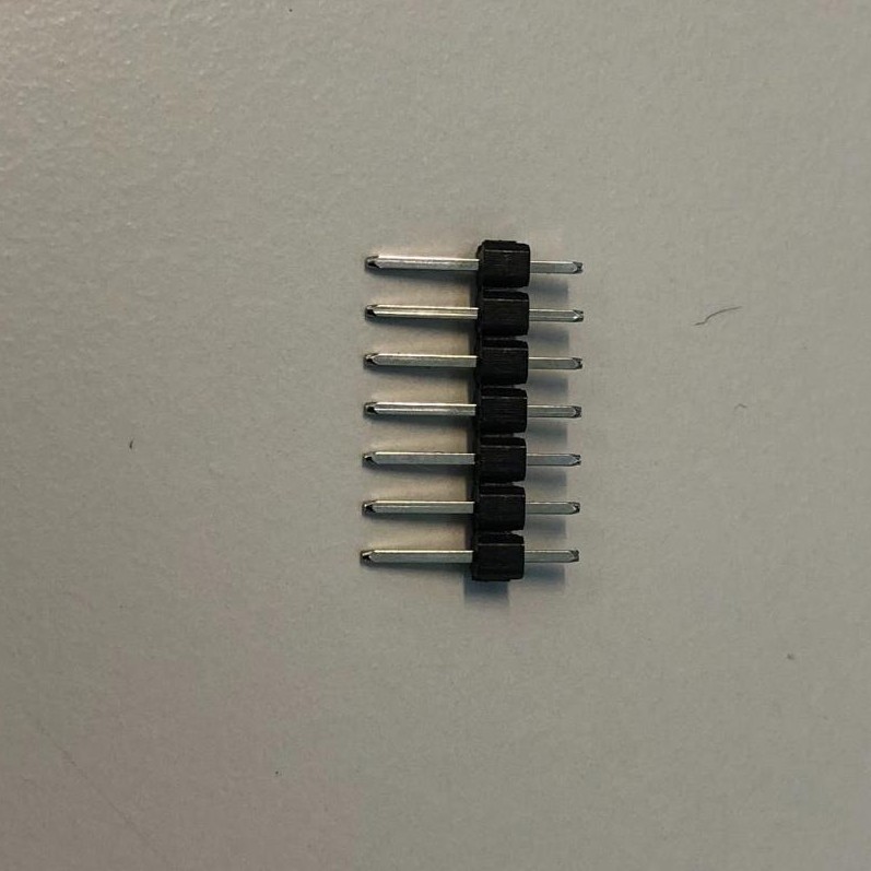
Fig. 2 Pinheaders#
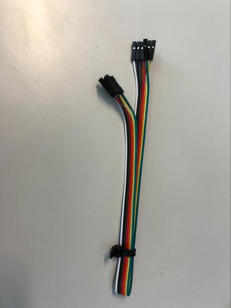
Fig. 3 Jumper Cables#
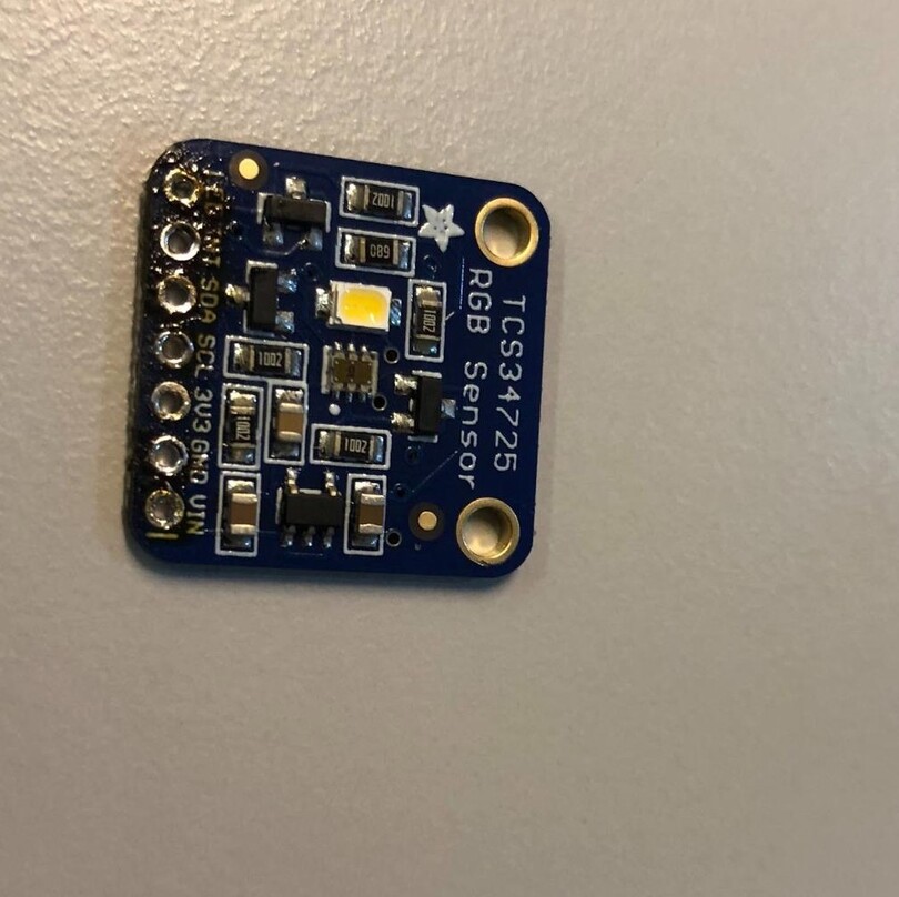
Fig. 4 The sensor#
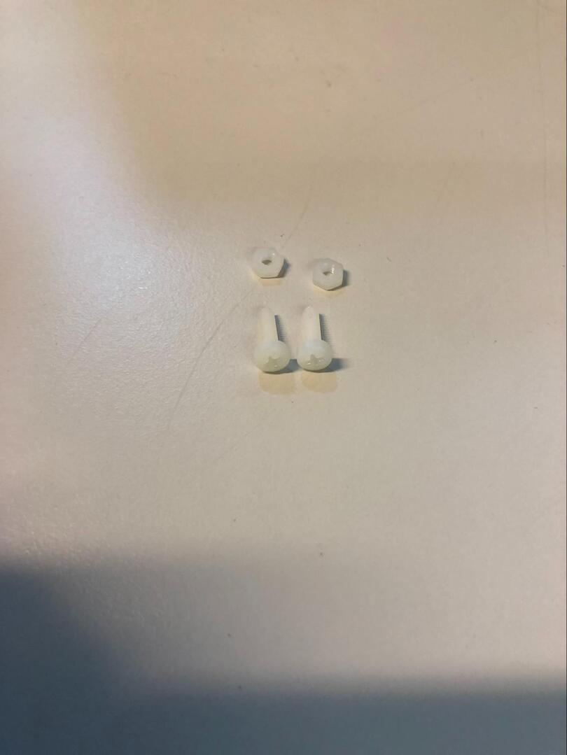
Fig. 5 Screws#
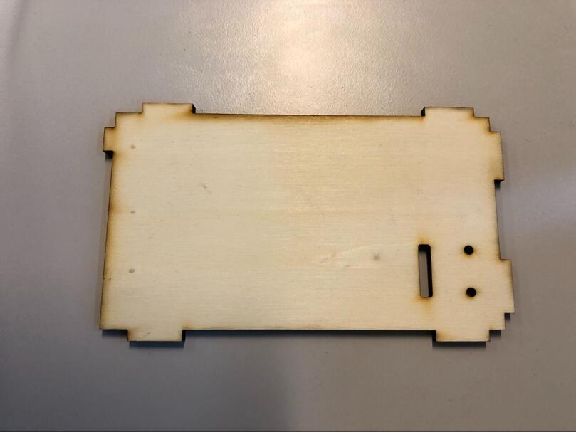
Fig. 6 Watchtower top plate#
Note
The upper plate of the watchtower need appropriate holes to fit the sensor.
1 - Soldering#
The first thing to do is to solder the pin headers to the actual sensor.
Tip
The easiest way to solder the pin headers is to use a breadboard and cut a few pin headers in order to get a 90-degree angle between the sensor and the pins.
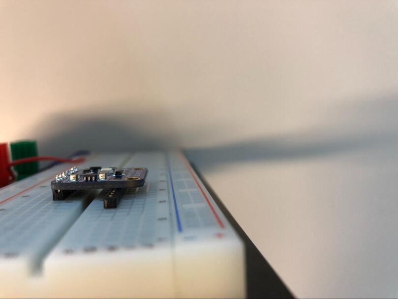
Fig. 7 Sensor on breadboard#
2 - Fixing the sensor to the top plate#
Slide the pin header through the large hole and fix the sensor in place with the screws.
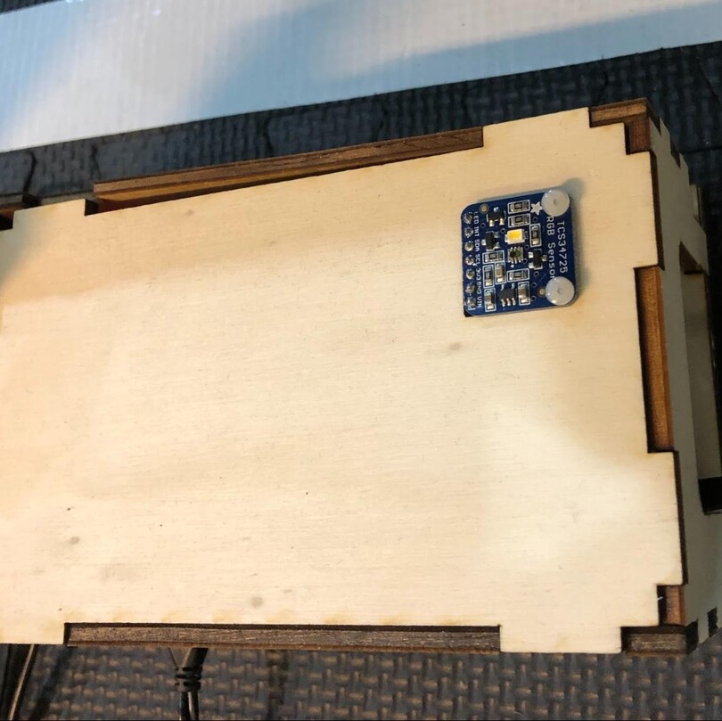
Fig. 8 Final assembled sensor#
3 - Wire the sensor to the Raspberry Pi#
The best way to figure out how to do this is to always take the sensor and turn it until you can read what is written on it and that will be our basic position.
This is the pin layout, every number corresponding to a wire color (it doesn’t matter which color is which number, just make sure that the wire is connected to the right pin header).
Connections on the Raspberry Pi:
o o 1 o o

2 3 4 o 5
Connections on TCS34725:
o 1 2 4 3 o 5
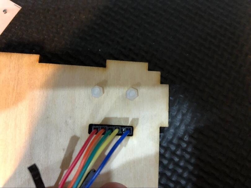
Fig. 9 Pin header Adafruit TCS34725#
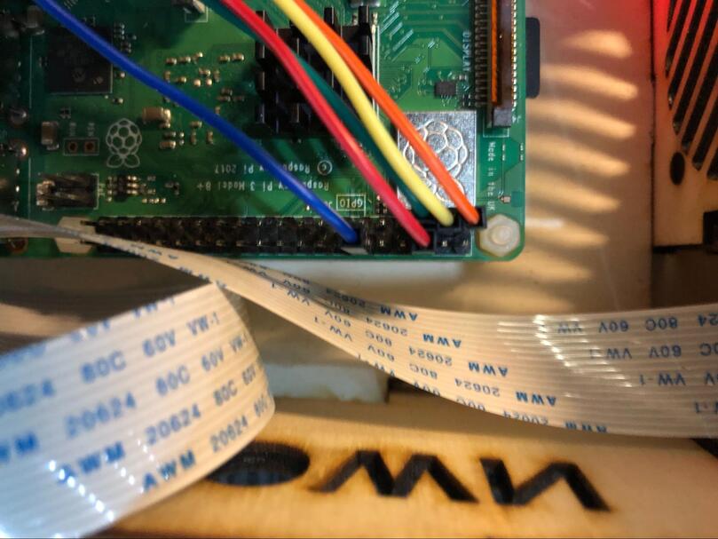
Fig. 10 Pin header Raspberry Pi#
You successfully wired the light sensor.